Audio upgrade
I LOVE clean sound, and LOUD on occasion. We’ll be living in the van full-time, with much of that time stationary, so having good quality audio is a good investment for us. And I’m excited to finally be able to listen to WMA and FLAC files on the road.
My van started with a 4.3” Sync 3 audio trim with tweeters in the pillars and rear speakers in the rear doors. Installation instructions would be different for different audio trim levels.
I installed a Pioneer head unit, Morel speakers front and rear, an Alpine amp, and a JL subwoofer.
Power for the amplifier and head unit come from the coach batteries, not from the van battery. The stereo draws about 4 A, and I didn’t want to be running down the van battery when parked for long periods of time.
The front speakers are installed in the factory locations.
The rear speakers are installed facing the rear on a Van Compass shelf over the cab. These are the primary speakers we’ll use for listening to music and watching TV while hanging out in back.
The amp is installed under the passenger seat.
The subwoofer is installed in a custom MDF/fiberglass subwoofer box in the right rear door.
The Maestro integration delivers tire pressure and other gauges to the head unit, which is nice.
Apologies for the long blog post. I never know what to leave out.
Materials
First, a big shout out to Crutchfield for great product selection, pre-purchase consultation, pricing, and outstanding customer support during the whole process. They were quick to ship out a replacement for a defective tweeter, and nearly everyone I talked to on the phone seemed very knowledgeable about my specific problems.
Pioneer AVH-4400 NEX Head unit: https://www.crutchfield.com/p_130AVW4500/Pioneer-AVH-W4500NEX.html?origitemno=1304400NEX. Supports Apple CarPlay, factory tire pressure and temperature gauges, rearview camera, USB and SD input.
Retain steering wheel controls, backup camera, and connect to factory harness: https://www.crutchfield.com/p_794ADSMRR/iDatalink-Maestro-ADS-MRR-Interface-Module.html, https://www.crutchfield.com/p_794HRRF02/iDatalink-Connec-HRN-RR-FO2-Factory-Integration-Adapter.html
Connect head unit to Maestro harness: https://www.crutchfield.com/p_264PASCON/Crutchfield-ReadyHarness-Service.html
Dash trim kit for Ford Transit: https://www.crutchfield.com/p_120995835G/Metra-99-5835G-Dash-Kit-Gray.html
Front speakers: https://www.crutchfield.com/p_210TU602/Morel-Tempo-Ultra-602.html
Front speaker Ford mounting bracket: https://www.crutchfield.com/p_120825605/Metra-82-5605-Speaker-Mounting-Brackets.html
Front speaker pigtail: https://www.crutchfield.com/p_120725602/Metra-72-5602-Speaker-Wiring-Harness.html
Rear speakers: https://www.crutchfield.com/p_210TU602IN/Morel-Tempo-Ultra-602-Integra.html?search=morel+602&avf=N. These are installed in the cabinet over the cab.
Amplifier: https://www.crutchfield.com/p_500PDXV9/Alpine-PDX-V9.html. A 4 channel + subwoofer amp, compact, fits under Passenger seat.
Subwoofer: https://www.crutchfield.com/p_13610TW3/JL-Audio-10TW3-D4.html. This is a 10 inch subwoofer with a mounting depth of only 3.25 inches. Fits in back door with custom subwoofer box.
Subwoofer connection binding posts: https://www.amazon.com/gp/product/B0002KR3X0/ref=ppx_yo_dt_b_asin_title_o05_s00?ie=UTF8&psc=1
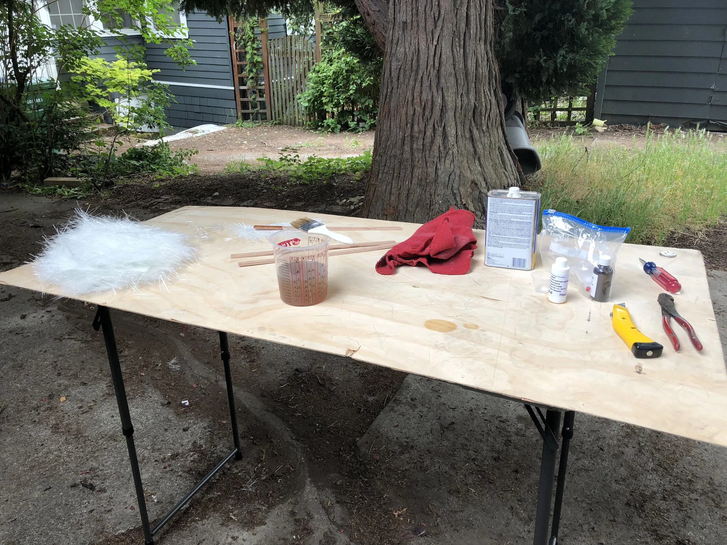
Fiberglass resin, 1.5 ounce chop mat: http://fiberglasssite.com/premium-polyester-resin-1-gal-39-95/, http://fiberglasssite.com/chopped-strand-mat-1-5-oz-50-5-yards/,
Subwoofer grill: https://www.crutchfield.com/p_136GR10TW3/JL-Audio-SGR-10TW3.html
Patch cables to connect the amp and head unit: https://www.crutchfield.com/p_007CMER206/Crutchfield-Reference-2-Channel-RCA-Patch-Cables-6-foot.html
Sirius tuner: https://www.crutchfield.com/p_220SXV300/SiriusXM-SXV300V1-Tuner.html
Sirius antenna to Ford adapter: https://www.crutchfield.com/p_794ANTSAT1/iDatalink-Maestro-SAT1.html
3.5mm female to male extension cable: I ordered one from Amazon, but when I plugged it in and turned up the volume with no music playing, I could hear noise and buzzing on the line. I ended up going to Best Buy.
3.5mm male to female splitter. Same issue here, the cheap Chinese one from Amazon was noisy when I turned up the volume, but I did have an old RadioShack splitter lying around that I used.
Marine plywood for sides and face of subwoofer box
Tools
Fish tape: https://www.crutchfield.com/p_042DM4533/Pro-Fit-Wire-Worm.html
Wire strippers
Crimpers
Speaker connectors
2” blue painters tape
Nitrile gloves – 5 mil
3x 1 quart mixing pot and stirring sticks
Loom tape and zip ties
Jigsaw with metal blades
Paint pen
Prep
Before beginning the install, I did some prep:
I had previously run 12awg subwoofer wire from the rear door to under the passenger seat
I removed the a pillar trim, pillar cupholders, glovebox, main console, the trim around the steering wheel underneath.
Removed the passenger seat
Amplifier install
The amplifier was installed under the passenger seat.
I already had positive coach battery power for my B2B charging system under the driver’s seat, connected to the main Ford bus with a 250A breaker and 4/0 cable. I installed a 4awg cable from the coach side of the 250A breaker to an 80A breaker just for the 4awg cable, and from that breaker ran the wire under the vinyl floor from driver to passenger seat. I found room to run this wire just in front of the emergency brake where it bolts to the floor.
Once the positive 4awg wire entered the passenger seat area, I installed an 80A relay. This relay is controlled via a switch on the main DC panel, so that the amplifier and head unit can be completely shut off (including memorized station presets) for extended parking or when power is scarce.
The negative 4awg wire was connected to the spare bolt on the negative terminal of the battery. With my floor installed, I found it impossible to get to the Ford recommended grounding point under the vinyl floor between the seats.
More details on the power supply in the wiring diagram below.
Now that the amp is powered, it was time to run wires from the amp to the head unit. I ran these wires:
Eight wires for the front/rear left/right speakers, all 14awg
A 14awg signal wire that is used by the head unit to turn the amp on and off
A 12awg power wire to power the head unit from the coach battery. This wire is fused with a five amp fuse adjacent to the relay.
3 coaxial RCA cable pairs – front L/R, rear L/R, and subwoofer
Before putting the floor in, I had previously run a 12awg wire from the rear door under the floor to the passenger seat for the subwoofer.
I used the worm to fish under the vinyl on the right side of the transmission hump, and from there up inside the dashboard. There’s a small opening in front of the right side vent to feed wires to the Pioneer. The space under the vinyl floor and exiting the hole in the dash was a little tight, so I didn’t bother twisting the speaker wires in pairs to reduce interference. The Crutchfield worm tape was really helpful here.
To mount the amp, I first had to get it high enough above the floor to clear the seat base sheet-metal. I took two pieces of 7”x7”x3/4” inch plywood and glued them together to create a 1.5 inch shim. I used 3M 5200 to glue this 1.5” block to the floor. I had previously cut away the vinyl under the passenger seat when installing the Webasto heater, so I had a good gluing surface.
I cut a piece of half-inch plywood the size of the amp and screwed that plywood to my shim. Then I screwed the amp down to that plywood. I put some grommets between the amp and the plywood to improve airflow underneath, although the instructions did not call for this. The amp maxed out at about 135° surface temperature, so it seemed like a little airflow wouldn’t hurt.
Front speaker install
Faroutride has a nice summary of their component speaker install here: https://faroutride.com/speakers-upgrade/
I tried to get fancy by tracking down where the tweeters spliced out from the door speakers in the factory wiring and use the that wiring. I placed the crossovers under the dash on either side, and used the factory tweeter and door speaker wiring. This approach ended up being more work than installing the crossovers in the doors and running new wires from the doors to the tweeters.
I will say that Antoine understated the difficulty of removing the drivers A pillar trim. The Ford repair manual says to throw this trim in the garbage and install a new piece if you remove it – because they designed it be very difficult to remove without breaking the mounting clips. Nevertheless, I was able to remove it and it seems to have gone back together okay.
I added Thinsulate to each door at the same time. This is important both for thermal and acoustic insulation – the speakers will perform much better with this layer in place, and it keeps the weather plastic from rattling as well. I also put some dynamat behind the speakers to further deaden the panel.
Here’s the wiring diagram for the front speakers:
Rear speaker install
I ordered my van with rear speakers in the rear doors, with the intention of removing them but using the existing wiring to install speakers on a shelf over the cab.
I opened up the main loom about halfway towards the back of the van, located the four speaker wires, cut them, and pulled them out of the main loom. Then I rewrapped the loom with new Tesa loom tape. Note that the wire colors on the speakers themselves are different than the wire colors inside the loom. Ignore the rear speaker wire colors, and use the wiring diagram below.
I installed a 1/2” marine plywood face on the Van Compass shelf. I lined the bottom of the shelf with 3/8” close cell foam to seal up the enclosure. I also installed Boom Mat baffles around each speaker.
Here’s the wiring diagram for the rear speakers:
Head unit install
This was complicated. There were a lot of wires, connectors, connection points. The Crutchfield “ready built” harness saved me about an hour of time doing crimps and probably some mistakes as well. Here are the key connections I had to make:
Connect the iDataLink Maestro to the Ford factory harness – two different plugs
Cut the yellow wire (which provides always on power to the Maestro), and splice that yellow lead into my coach power (wire previously run from the amp)
Because I’m using my own amplifier, I cut the speaker wires between the Pioneer and the Maestro unit, and spliced in the amplifier speaker wires. Aftermarket head units use a standard wiring color which is:
I wanted the option of turning the radio on without the key in the ignition. Even though I was providing power to the Maestro unit, the Maestro unit does not power on the Pioneer unless it receives an accessory on signal from the Ford BCM. Maestro support instructed me to insert a switch between the red and yellow wires leading from the Maestro unit to the Pioneer. I mounted the switch just in front of the Pioneer on the dashboard. The Maestro unit does not turn on without the key, so any Maestro related functions are not available. I think this only affects the steering wheel controls and the Ford Sync stuff.
I wanted to use my factory Sirius antenna, so I installed the antenna adapter to convert from Ford to standard, and then plugged this into the back of the Sirius tuner. I then plugged the Sirius tuner into the back of the Pioneer.
The Maestro had a 3.5mm output that needed to be hooked up to the pioneer auxiliary input to preserve the Ford Sync microphone. In hindsight I don’t think I’ll ever use the Ford Sync system again, but I didn’t want to burn any bridges at this point.
When playing back videos on my laptop or TV using the stereo for sound there was a two second lag between the audio and the video. Bluetooth was unacceptable for video playback. I needed to use the same Pioneer auxiliary input that I had previously used for the Ford Sync mic for a wired audio connection, so I added a 3.5mm splitter, and then ran a 6 foot female to male 3.5mm cable. I did not hear any reduction in sound level with both devices connected. The female side of this cable was attached to the Transit dashboard at the media port location. Remove this trim piece, and there is a plug on the backside that can be removed, and then drilled out to accommodate the female side of the connector. I glued this in with 3M 5200. Now any 3.5 mm source can be used with the stereo. As mentioned above, use high quality, shielded wires for this auxiliary input or you will get noise on the line.
With the Ford Sync head unit gone, the OEM USB port was dead. Pioneer provided a USB cable. I used my bench grinder to shave down the female side of the cable until it would fit into the Ford USB trim piece. I glued it in with 3M 5200 – just a couple of spots – as this cable would have to be removed if the dash were being removed for service.
Connect the rear camera feed from the Maestro to the Pioneer.
Connect the 3 RCA pairs Front L/R, Rear L/R, and Subwoofer from the amp to the Pioneer
Connect the Ford radio antenna
Install the Pioneer microphone for CarPlay. I installed this microphone by clipping it into the headliner trim above and in front of the rearview mirror, tucking the wire in above the headliner over to the driver side a pillar, and then running underneath the dash into the back of the Pioneer. Although it’s a bit further away from my mouth than the sun visor, there was not enough cable to go the extra distance and I wanted the cleaner look with no exposed wires. So far the audio sounds okay on phone calls. If I was using this van for conference calls while driving for work I would probably do it differently.
Hook up the Maestro OBD2 connector to the Ford OBD2 connector. With the Maestro plug in place, it is not possible to use a Bluetooth OBD2 connector at the same time. Since I am getting tire pressure and engine coolant temperatures on the Pioneer head unit, and I can easily unplug the Maestro plug if needed, I’m going to leave it plugged in for now.
Connect the Pioneer amplifier on/off wire to the amp
The Sirius tuner and any unused RCA plugs and wires were secured behind the Pioneer on the dashboard. The Maestro and all other wiring harnesses were crammed underneath the Pioneer. Zip ties and loom tape compacted it enough to allow the radio trim piece to fit.
I ended up testing all of these functions multiple times, as with all of the pushing and shoving and test fitting, I was worried something would shake loose. I had to test:
FM radio reception
AM radio reception
Ford Sync 3 functionality – make and receive calls, view Ford OBD2 gauge information, provide Ford sync commands. Curiously enough, even with the Ford head unit gone, the Ford Bluetooth module, microphone, and audio audio output are still in place, so you have the potential of using either Bluetooth system to make and receive calls. Of course this greatly confuses the head unit when receiving a call – which system takes priority? So I’m committing to using Apple Carplay.
Apple CarPlay functionality – make and receive calls, play music
Steering wheel controls – confirm volume and track skip are working, dash gauge controls are working
Backup camera – place transmission in reverse and confirm video is streamed to Pioneer
Auto on/off – turn key on and off and verify unit powers up and down based on accessory power. Also verify that station presets are preserved after power has been shut off.
Permanent on/off - turn on the permanent power switch and verify unit stays on with no key in ignition.
Sirius reception
Auxiliary input via laptop – play videos, confirm no lag
USB input - play music from a USB drive
Confirm that all four speakers plus Subwoofer are wired up correctly by using the fader/balance controls. During this test site discovered that I had mixed the grounds for two of the speakers, which was quite the puzzler. Moving the fader all the way to the front left one of the rear speaker still firing.
Confirm that amp turns on-and-off with the Pioneer
Drive test, confirm no ground loops, hums, or other feedback with heater blower running, AC on, etc.
I’m not real happy with the fit of the Metra dash kit. The radio trim piece looks great, but the four plastic clips that are supposed to secure it to the dashboard don’t hold it down very tightly, and indeed leave about a 1/8 inch gap underneath. After several calls to Crutchfield, I finally removed the four white clips, pulled the metal clips off of the OEM trim piece and put those in there. This lifted the panel up even higher, but at least it wouldn’t come floating loose. It’s definitely a design defect on the Metra trim piece.
Subwoofer install
Although the van has a large interior space, I already had all the wall space allocated for cabinets and storage, the space under the driver seat had the battery and B2B charger, and the space under the passenger seat had the amplifier and heater.
I decided to install a shallow mount subwoofer in the right rear door. Even though the subwoofer is all the way at the back of the vehicle, low-frequency sound travels well through vehicle interiors.
For the tightest bass response, I decided on a sealed enclosure. https://www.crutchfield.com/S-aLC9ICebMeW/learn/car-subwoofer-boxes.html
There seem to be two primary types of subwoofer enclosures – fiberglass and MDF. MDF enclosures are good for rectangular shapes, while fiberglass enclosures are good for irregular shapes. I was dealing with one surface – the rear door – which is an irregular shape, but the sides and front of the enclosure were regular. To minimize the labor-intensive fiberglass portion, I built a hybrid box where the back is fiberglass, and the sides and front are three-quarter inch marine plywood. If I tried to do a flat back, I would’ve lost valuable cubic inches. I recommend marine plywood over MDF in a high moisture environment like a door. MDF expands and crumbles on contact with water.
Select a subwoofer that requires a minimal enclosure volume and has a shallow mounting depth. The 10 inch JL Audio subwoofer I selected has a mounting depth inside the box of 3.25 inches, and a total volume requirement of .519 ft.³. I found it easier to work in cubic inches, so .519 ft.³ is 896 in.³.
Calculate the size of box you need and determine if it will fit in the rear door space available. Remove the rear door trim and existing rear speaker if you have one, disconnect and tape or zip tie any wires or door lock cables that are in the way, and then figure out the maximum height and width of the subwoofer box. I came up with about 18 inches wide, and 16 inches tall. Factoring in the three-quarter inch thickness of my material for the box walls gave me an internal of 16.5 inches wide, and 14.5 inches tall. Dividing 896 by 16 .5 and 14.5 gave me a required depth of 3.75 inches. This looked doable. I also had to factor in any space consumed by internal bracing – subs produce a lot of vibration so the box needs to be really rigid, and I didn’t really want my back door panel thumping and vibrating.
Use a jigsaw with a fine metal tooth cutting blade and cut out a big square in the rear door. Paint the edges to prevent corrosion.
Run 12gauge speaker wire from your amplifier through the rubber loom and into the back door.
Determine the final location for wires and door cables and tape or zip tie them into place. It’s okay to run wires behind the subwoofer enclosure if necessary, although you do sacrifice some internal space. However, I had to move the manual door lock cable by drilling a new hole closer to the open side of the door and reroute the cable to avoid the enclosure entirely.
Use a scribing jig and 7 inch wide strips of cardboard to create templates for the left and right sides. The back of the van door is pretty curvy, so I had to rough trim my cardboard templates first before I could trace the exact outline of the door with my scribing jig. I cut the templates extra deep to ensure the enclosure would have enough volume. I trimmed it at the end.
Cut out the sides out of the marine plywood, and attach them to the van sheet-metal using 2 1 inch aluminum angle brackets on each side. I fastened the back side of the sides about 1/8 inch away from the exterior sheet-metal. I just used sheet-metal screws initially, but given the high vibration environment and the poor holding quality of sheet metal screws, I ended up gluing 1x1 marine plywood blocks to the backside of the screw holes with 3m 5200 to give the screws more bite and prevent them from loosening up over time.
Now that you have the final dimensions and locations of the left and right sides, make templates for the top and bottom, then cut them out of the marine plywood.
Drill pocket holes and attach the top and bottom to the sides.
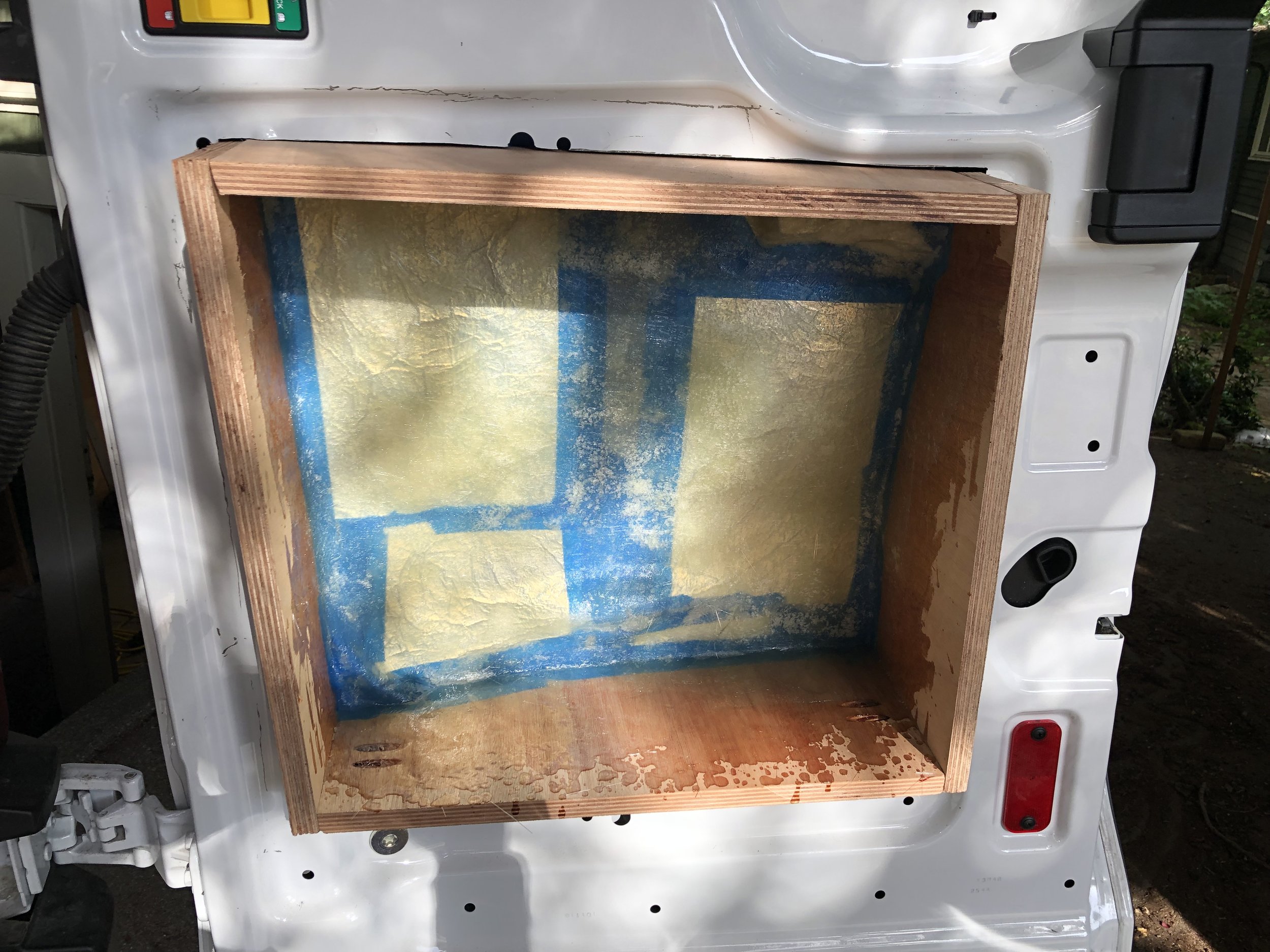
Prepare the area to be covered with fiberglass by applying blue tape at least two layers thick over the van sheet-metal and any wires or other fittings that you will be covering up.
Apply some large swatches of tinfoil over the blue tape to provide an easier release after the fiberglass cures.
Tear up a bunch of 7” squares of the 1.5oz chop mat.
Mix up the resin: https://www.youtube.com/watch?v=Eam1wyctO3Y
Using a chip brush, apply a coat of resin to the back and sides of the enclosure.
Start applying squares of fiberglass, and use the chip brush to stipple the resin into the mat.
Cover the whole back and partway up the sides with fiberglass and resin. You may find it’s harder to get good coverage on the top side as it tends to run down the back. You can thicken up the upper area on the final coat after it’s removed from the vehicle.
Let the fiberglass harden up a little, and apply another layer.
Wait some more, and apply another layer.
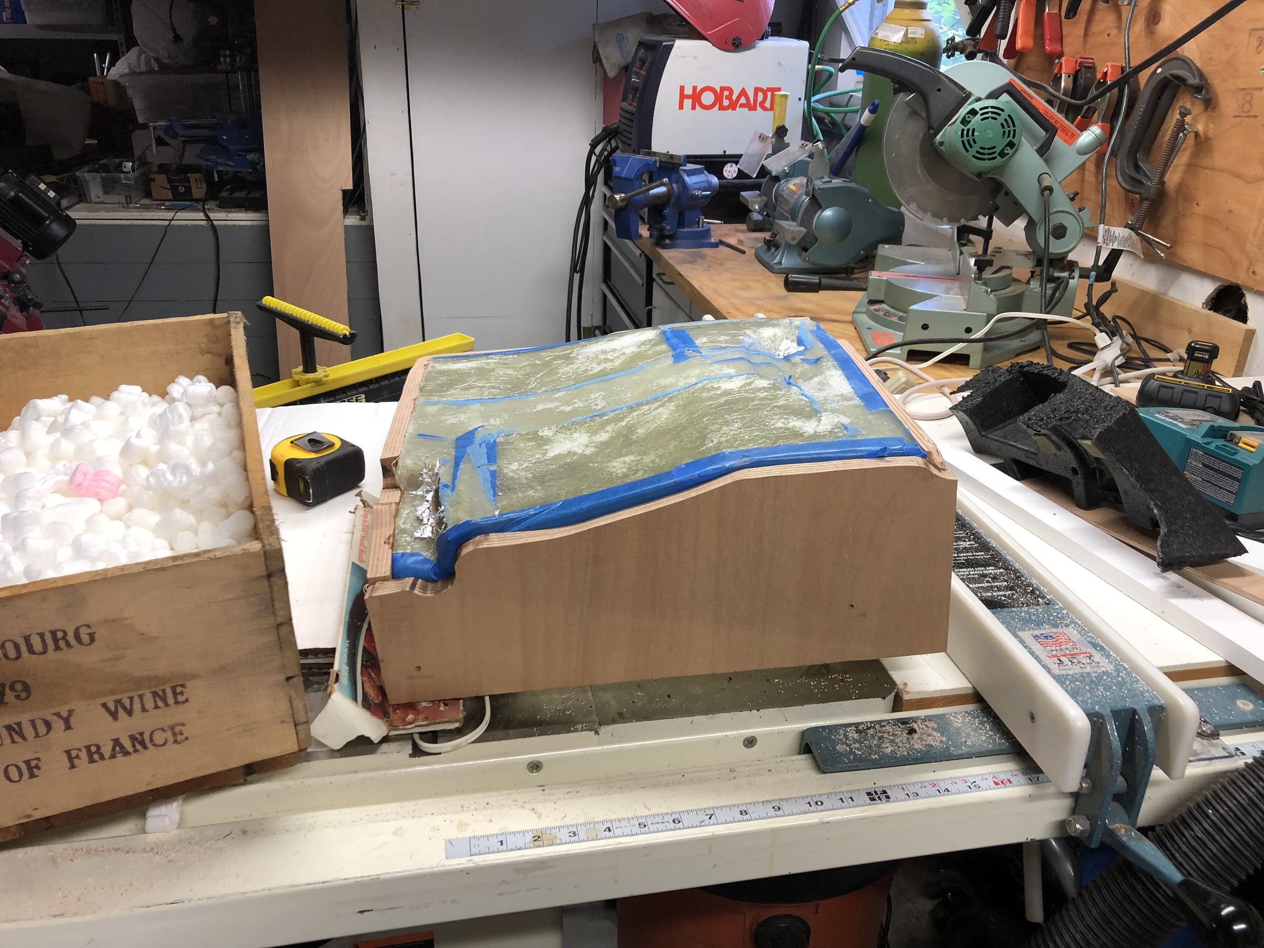
Let it cure overnight, then remove the enclosure from the van.
Apply the final layer, and check for thin spots or any spot that isn’t completely rigid. Ideally you have a minimum of 4 layers everywhere.
Let it cure overnight.
To calculate where to trim the face to get a .519 cubic foot volume, I first calculated .519cf in a normal cardboard box, and filled it up to that line with packing peanuts. Then I poured those peanuts into my enclosure, and marked a line indicating the correct depth for .519cf.
Trim the sides of the box down to match .519cf.
Loom tape the wire, and check the rest of the interior of the door for any loose wiring or fittings. The subwoofer generates a LOT of vibration, so you want everything locked down as much as possible.
Cover the back of the enclosure with 1/8” foam, or the interior of the door with dynamat.
Do a test fit of the box. In my case, the sides ended up almost flush with the van metal, so I had to turn my angle brackets around and mount them extending into the door.
Cut a ¾ face panel out of marine ply.
Cut a circle in the face for the subwoofer opening. I placed my subwoofer in the upper left corner as that seemed to be the location that would provide the best sound flow to the front of the vehicle.
Run a liberal bead of caulk around the end grain of the enclosure sides, and screw the enclosure face to the sides. The caulk provides an airtight seal.
Wire up the subwoofer (I had to bridge two voice coils), and create a pigtail long enough to extend out of the enclosure. Tie a knot in the pigtail close to the left side of the enclosure, and then run the wires out through a small hole. You’ll want to caulk the hole to prevent any air leakage. I used binding posts myself, but I think the wires are easier and create fewer failure points.
Attach the pigtail to the subwoofer, and screw the subwoofer to the enclosure.
Using quick disconnect crimp fittings (or binding posts), attach the wires already in the door to the ends of the pigtail sticking out of the enclosure.
Screw the angle brackets into the holes with the plywood backing plates
Drive test
After adjusting the amp and setting the correct gain for all channels, I cranked up some Steely Dan and Steel Pulse. Sound is excellent, tight bass, good mid range and highs.
For the driving experience, there is some muddiness from van noise, and the usual imaging strangeness with having the tweeters so far from the mid range, but overall a wonderful improvement over the stock system.
And when hanging out in back it’s a really nice listening environment.
Some comments and minor issues:
I don’t like the design of Apple CarPlay, particularly with Google Maps. I can no longer pinch and zoom while driving - the phone screen is locked, and the pioneer unit doesn’t support this. Apparently this might be fixed in iOS 13. We’ll see.
I like having steering wheel access to tire pressure and other gauges.
When I really crank it up, anything loose in the back rattles - stuff on the floor, tail lights, door locks, etc. Once the bed and its 5” foam mattress are in, along with the water tank, bench seat, and other fixtures, I expected that the rattling won’t be noticeable to me even at high volumes. I don’t hear any rattling at normal volumes.
Jury is out on keeping the rear firing speakers on for extended driving in front. The imaging is muddied with the rear firing speakers sending sound back and reflecting around the mostly empty interior. But it is really nice to have them for hanging out in back.
The Pioneer screen blanks out sometimes. Music is still playing, but the screen is off. Not sure if it’s a Pioneer bug, or perhaps some interaction with my coach B+ and the Ford Acc+ routing through the Maestro. Haven’t had a chance to troubleshoot.