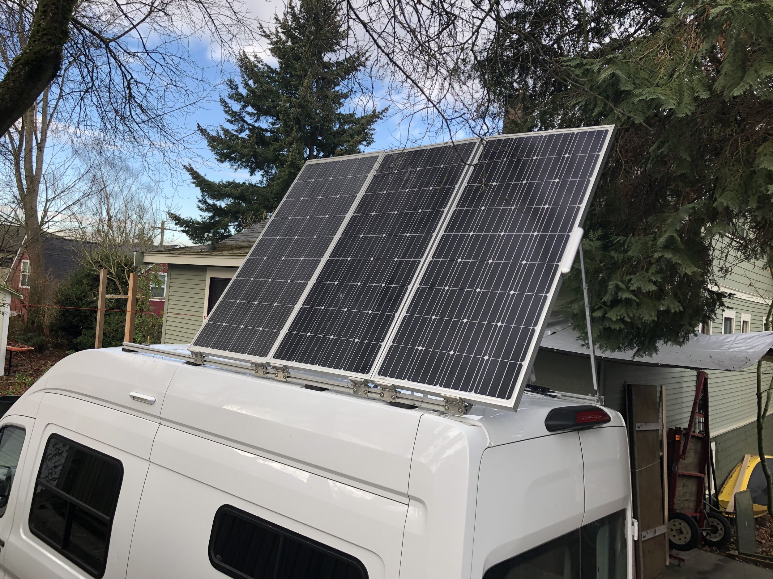
I’m installing three solar panels on the roof behind the MaxxAir fan for a total of 560 W of capacity. Because of the slope of the front part of the roof, there’s not a lot of roof space on the Transit, so the third panel will hang over the roof line a few inches at the back of the vehicle. Apparently I wanted capacity more than complete stealth. If you’re curious about my design process and the overall electrical system, check out my Electrical Plan.
I am installing the panels on my existing roof rails – two 102” long 8020 aluminum extrusions bolted to the roof using Hein’s brackets. More information on this here: https://sunlightandtrees.com/blog/design-roof-rack.
The solar panels will be tiltable in either direction. Gone with the Wyns have a nice video showing a 30% increase in power when tilting. For my latitude (48 degrees north), the ideal winter tilt is 72°, and the ideal summer tilt is 20°. I didn’t feel comfortable with the stability of a 70° of tilt so I’m planning a range of 30° to 60°. This site was helpful for planning tilt: https://www.solarpoweristhefuture.com/how-to-figure-correct-angle-for-solar-panels.shtml.
I had a number of design constraints that made this project more challenging:
All 3 panels must tilt without shading each other, even in early morning and evening sun. This meant the panels had to tilt on the long edge rather than the short edge which is more common and for which there are brackets and legs available.
I wanted to use 8020 rails for mounting the panels as I am also mounting an awning, antenna, and potentially other items using the same rails. But using these rails prevented me from using off-the-shelf tilting solar mounts such as those sold by AM Solar.
I wanted the panels to set low on the roof for less wind resistance and lower profile.
I am using 4 stainless steel hinges per panel, four aluminum angle brackets per panel, and two adjustable legs per panel.
I spent quite a bit more time than anticipated with this design. It's functional and robust, but I'm not sure I would take the same approach over again.
I used a fairly large junction box from AM Solar (https://amsolar.com/rv-combiner-box/20-roof) as I will be running the wiring for three panels, a rear facing light, and a cell booster antenna. Having this junction box makes it easy to modify the electrical system without punching new holes in the roof. You can also use the junction box to experiment with changing panel wiring from parallel to serial, and the homerun approach means that every panel gets its own 10awg run, rather than aggregating through pigtails as is sometimes done.
Materials
Two Grape Solar solar panels – 180 watts each. https://www.homedepot.com/p/Grape-Solar-180-Watt-Monocrystalline-PV-Solar-Panel-for-Cabins-RV-s-and-Back-Up-Power-Systems-GS-STAR-180W-US/301024442
One High-tech solar panel – 200 watts. https://www.ebay.com/itm/200-25-Watt-12-Volt-Solar-Panel-Off-Grid-RV-Boat-highest-power-12V-you-can-buy/264048386965
AM Solar rooftop wiring kit. Kit contains junction box, butt connectors, 2awg mains wire, 10awg outdoor UV rated panel wire, MC4 pigtails.
Tube of blue Loctite and tube of anti-seize compound. Remember to use one or the other on ALL stainless steel nuts and bolts! Otherwise you may get galling, where the parts cannot be separated without grinding them off.
One tube of Dicor self-leveling lap sealant
8” by 8” sheet of 1/8” PVC plastic to make a roof shim for the junction box
Can of PVC cement
4x VHB backed zip tie mount. https://www.hellermanntyton.us/products/151-01634/. For securing panel wiring to roof.
Hinge hardware
12 Stainless steel hinges https://www.amazon.com/gp/product/B07BQ1JQW2/ref=oh_aui_search_asin_title?ie=UTF8&psc=1
36” of 7 mm stainless steel rod. https://www.ebay.com/itm/304-Stainless-Steel-Rod-7-mm-Diameter-043mm-x-36-Inch-Length/111748073105
24 cotter pins and rings.
24 5/16” x 1” button head stainless bolts and 24 5/16 stainless locknuts (for bolting the hinges to the panels)
24 5/16” x ¾” button head stainless bolts (for bolting the hinges to the rails). See note below – all of this 5/16” hardware could have been 1/4” hardware.
24 5/16” stainless steel t nuts for 1.5” 8020 extrusions (the roof rails)
48 5/16” stainless steel washers
1” x 3’ x 1/8” aluminum bar (to shim out the solar panels to align with rack)
1” x 3’ x 1/4” aluminum bar
1” x 3’ x 3/6” aluminum bar
1” x 3’ x 1/6” aluminum bar
1” x 3’ x 1/6 aluminum sheet (onlinemetals.com has a nice aluminum sample pack that works great for shims)
Tilt leg hardware
6x 1”x 28”x 1/8” aluminum angle (this is the bottom half of the tilt leg)
6x ¾”x 36”x 1/8” aluminum angle (this is the top half of the tilt leg)
50” of 1.5”x 1/8” aluminum angle (this will be cut into angle brackets and attached to the underside of the panel and the roof rails)
24x ¼”x 3/4” stainless bolts (for bolting the upper and lower half of the legs together, and bolting the angle brackets to the panels)
24x ¼” stainless lock nut (could use wing nuts if you are frequently changing leg length based on travel)
48x ¼” stainless washers
12x 5/16” x 1” stainless carriage bolts (will slide into 8020 rail, angle bracket will bolt to it)
12x 5/16” locknuts and washers (to bolt the lower angle brackets to the rail)
Tools
Drill press for enlarging the holes in the stainless steel hinges, drilling cotter pin holes in the stainless steel rod
Screwgun for drilling 104! holes in aluminum
Tablesaw or jigsaw for cutting the plastic shim
Mineral spirits for cleaning up the hinges after removing the pins
Wrenches, sockets, and hex keys for the bolts
Metal bandsaw or jigsaw for cutting the stainless steel rod and aluminum shims
Contour gauge to create a shim for the junction box. Could also just make a template out of cardboard.
Bench grinder for cleaning up rough edges and deburring holes. Could also use a file.
Wire connector crimper, cutter, and stripper
Green scrubbie and alcohol for surface prep
Good ladder with rags for padding
Stiff soled boots - you’ll be standing on the ladder for hours, hard on the arches
Vice grips and/or vice for bending aluminum
Process
Prepare the hinges
Remove the pins from the hinge. First pry off the pin cover on one side of the hinge using a pair of channel locks. Drive the pins out by using a smaller diameter bolt and a small hammer. I found it easiest to screw a piece of angle iron to my workbench, and then clamp the hinge to the angle iron. I drilled a hole through the bottom of the angle iron to give the pin a place to move to as it passed through the hinge.
Clean the hinges to remove the gummy stuff holding the pin in place by soaking them in mineral spirits and running a small bottle brush through them.
Place each half of the hinge in the drill press and drill out the two outside holes to accommodate a 5/16 bolt. Use a slow drill speed and cutting oil. I had to re-sharpen my bits several times during this process. Deburr the holes using a deburring tool or bench grinder. NOTE: I was somewhat ignorant of 8020 when starting this, and didn’t realize that although they standardize on 5/16 bolts for the 15 series extrusions, you can just as easily use ¼-20 t-nuts and hardware. This would’ve saved me drilling out the hinges, and the bolts would’ve been slightly cheaper.
Cut the stainless steel rod into 4” lengths and drill a hole in each end for the cotter pins and rings. Oversize the hole a bit to make it easier to insert and remove the pins. Deburr the ends and holes.

Hinges installed with shims.
Prep the wiring for the solar panels
If you used the AM Solar kit, you’ll have MC4 pigtails to attach to the MC4 connectors of the solar panels. This makes it easy to swap panels, switch from serial to parallel, etc. You can also just use butt connectors and cut off the MC4 connectors entirely.
Calculate the desired wire length for each panel. Because these panels are tilting in either direction, the wire for the solar panel will run to the middle of the panel and be zip tied to a hole in the rim of the panel. 25” of slack will be left so that when the panel is raised there is wire available. The wire then runs down the middle of the roof of the van until it reaches the area of the junction box. Leave plenty of slack in your wire run – it’s easier to trim than add!
Attach the MC4 pigtails to each of the three solar panels
Attach the wire to the pigtails by stripping the ends, inserting into the butt connectors, crimping the butt connectors, and then heat shrinking. AM Solar adds another layer of protection by putting heat shrink tubing around the already heat shrunk butt connectors.
Drill a point in the rim of the panel mid span and then zip tie the wire.
Panel wiring routed to center of panel to allow tilting in either direction.
Fabricate the tilt legs
In this step we are drilling holes so the two pieces of aluminum angle can be used as an adjustable leg ranging from 30” to 60”. And then we are attaching bolts in brackets to the panel and rail.
Drill two holes exactly 4 inches apart, 1” from one end of the 6 ¾” aluminum angles.
Take a 1” aluminum angle, place it under a ¾” aluminum angle with a 6” overlap. Using the holes you already drilled, drill through the 1” aluminum angle. Note that the left and right legs are mirrors of each other - they are not identical. You should end up with 3 pairs of legs.
When these two pieces are bolted together, their total length will be 60 inches. You can drill additional holes at 4 inch intervals to allow the leg to be shortened.
At the other end of the 1” aluminum angle, drill a ¼” hole about ¾” from the end. This hole will be bolted to the roof rail.
Next step is to make the bottom of the 1” aluminum angle bendable so that it can be attached to the roof rail at an angle. To do this, you need a flat tab of aluminum at the bottom. Cut away the side of the aluminum angle for about 2”. Then place the end of the aluminum in a vice, or use a pair of vise grips to bend the 1.5 inch tab to a 30° angle.
Now drill ¼” hole at the top end of the ¾” angle. This will be used to bolt the top of the leg to an angle bracket on the under side of the panel.
Take the 1.5” aluminum angle and cut 12 1.5” long sections out of it.
Drill two 1/4” holes in the angle – one for bolting into the solar panel, and the second for bolting the leg.
Drill matching holes in the four corners of the underside of the solar panels, keeping in mind that the brackets must clear the roof rails, and that the face of the bracket must be inset from the edge of the panel by about 3/8” to leave room for a wingnut when the legs are attached.
Attach the angle brackets to the solar panels.
Place the 5/16” carriage bolts in each rail – 2 bolts per panel. I chose to place these bolts on the inside of my rail so that they were not visible from the ground. Unbolt the 8020 rails from their brackets, slide out the T nuts, and slide in the bolts and t nuts in the correct order. Each bolt is placed just to the outside of the hinge for each panel.
The top bracket bolted to the underside of the panel.
Using a short piece of angle as a drill jig for four-inch spaced holes.
Three-quarter inch and 1 inch angle bracket bolted together to make the leg.
The angled bracket leaves clearance for the wingnut.
Holes every 4 inches allow for adjustment.
Mount the hinges on the panels and roof rails

This panel needed a 1/8 and 1/4 shim.
Measure the total width from the outside edge of each rail at each of the mounting points on the roof. I didn’t do this step, and learned during the installation that the roof rails are not parallel. You should end up with six measurements which you will use to determine the thickness of the aluminum shims you will place under the hinges at each point on the solar panel.
Measure in 1” from each end of the panel, place a hinge on the panel for guidance, and use a center punch to mark the desired locations for the holes.
Drill the holes. Both brands of my solar panels had double wall aluminum frames, so I drilled through both layers.
Cut, deburr, drill holes for, and place the necessary shims so that your solar panel hinges are the same distance apart as the roof rail hinges.
Secure the hinges to the solar panels using the 1” button head bolts, washers, and lock nuts. You may end up having to remove some of these hinges based on shimming needs once the panel is on the roof.
Slide or drop in your T nuts on the side of the roof rails, and loosely attach the bottom portion of the hinges with the three-quarter” bolts and washers.
Place a blanket on the roof, walk up the ladder with the solar panel in place one end of it on the blanket. Slide the solar panel across the roof, and then walk around the other side of the van, grab the solar panel and drag it into its final location. This is easier with two people, but manageable with one.
Insert the pins into the hinges on this side, and then move back to the other side and check fit. You may need to add or remove shims.
Repeat for the remaining panels, leaving ¼” gap between them. Verify you can raise and lower each panel without having it bind on the neighboring panels. Verify that the pins will slide in and out. Mine are a bit tight, and I sometimes have to use an Allen key to push the pin out.
Make the junction box shim and secure to roof
AM Solar has provided some nice instructions for their junction box here. https://static1.squarespace.com/static/562bc73de4b0908330f67ee0/t/5942b9e28419c2dea968fdc9/1497545187324/RoofCombinerInstr.pdf
The solar panels are mounted so close to the roof that there is limited clearance for a junction box under the panels, so the best location ends up being at the edge of the roof where there are ridges in the sheet metal. Rather than piling up lap sealant to seal the junction box perimeter, I created a shim to create a closer fit. The shim also allowed me to extend the junction box out a bit around the hole in the bottom providing more sealant between the hole and any possible water.
Find the best location for the junction box under one of your solar panels. You will want the whole through the roof to be on a ridge rather than a valley, clearance for the wire to enter the junction box on all three sides, a good open spot inside the van on the ceiling for routing the cable, and perhaps not having any of the liquid tight fittings facing forward in the direction of travel. Make sure the solar panel can close over the junction box with the lid on.
Use the contour gauge to determine the width of the ridge in the sheet metal on the roof, and the width of the plastic strips you will place on either side.
Cut a shim out of the 1/8” plastic PVC sheet to fit the entire bottom of the junction box, but make it about three quarters of an” longer on the side where the wire will pass through the bottom of the junction box to the van.
Cut two strips of plastic, and glue them to the plastic sheet, matching the contour gauge dimensions
Glue this shim to the bottom of the junction box. All of these materials are PVC, so you can use the same cement.
Drill the correct size hole through the plastic shim depending on the gauge of your solar panel wire and any additional roof wiring you will be passing through. In my case I made the hole a rectangle, the same size as the hole in the junction box, using my Dremel.
Now drill or cut a matching hole through the roof.
Scuffed the roof with a green scrubber pad to take some of the shine off the paint where the junction box will be attached. Do the same for the plastic bottom of the junction box shim.
Liberally coat the bottom of the junction box with lap sealant.
Place the junction box on the roof aligning with your roof hole.
Before pressing down and squeezing out lap sealant, run a line of blue painters tape around the inside of the hole down into the van. This will prevent the lap sealant from squeezing through the hole.
Drill holes through the junction box and the roof for the four screws, and screw the junction box down.
Run ½” bead of lap sealant all away around the perimeter of the junction box.

Extra plastic around hole in junction box to provide a better seal

Shim contoured to roof

Lap sealant underneath and al and l around.
2awg cable enters the roof at the top, as does the LED light wiring.
Wire it up
I won’t repeat AM Solar’s instructions about wiring here. I will make some comments about wiring layout for tilting panels.
To support a panel tilting from either side, the wires need to run somewhere down the middle of the roof. So my foremost panel has the wire running to the middle of the panel on the aft edge where it is it tied to the panel. I tilted the panel to its maximum height to ensure I had enough slack. Then I put a VHB backed zip tip mount on the roof (scuffing the paint and cleaning with alcohol first). I loosely zip tied the first panel wire to the mount, and raised and lowered the panel to watch how the wire laid as I lowered it. I didn’t want it sitting on top of the adjacent panel are bunching up so that the panel could not be lowered all the way.
I repeated this for the other two panels, with each panel’s wire being added to the bundle from the foremost panel.
I drilled an extra hole in the junction box and installed an extra liquid tight fitting. This will allow me to install additional electrical accessories on the roof and run them through the junction box.
Each liquid tight fitting has two holes in the rubber grommet. I plugged the unused holes with short pieces of 10awg wire.
Another AM solar tip – for smaller gauge wires passing through these liquid tight fittings, you can put a few layers of heat shrink on them to bulk them up so that they seal tightly when passing through the fitting. I did this for my rear LED light.
Lessons learned
I would not use 5/16 bolts when mounting to the roof rack. ¼ t-nuts would work just fine, I wouldn't have to drill out the hinges, and the hardware would be a bit cheaper.
I would probably have some simple aluminum hinges fabricated locally that could work both for tilting and attaching the tilt legs to.
If you do end up purchasing hinges, try to find some with a standard pin size so that you can slide a long bolt in.


