Our propane system fuels our gas oven and hot water heater. A lot of people ask me why use propane for cooking and water heating instead of electricity. We are using a propane system in our he van because it is an energy dense system, providing many hours of cooking and hot water with y infrequent refills (every 1-2 months). We are saving our electricity for other needs. I also hear concerns about safety – but propane systems have been used on boats and RVs for many years and are very safe if installed and managed correctly.
The tank is installed under the vehicle adjacent to the sliding door on the passenger side. My goal was the largest tank possible without reducing ground clearance. Although it’s a tight fit, this tank fits perfectly in that space while still allowing for the installation of the passenger factory step and maintaining current ground clearance. 2 lines were run to where the stove and water heater will be located.
Safety
The following items are part of the safe design:
No fittings inside the vehicle except at the appliance, direct runs only. Tank is mounted exterior to the vehicle along with all fittings.
Solenoid valve on the high pressure side of the tank that will normally be in the off position unless we are using the oven or hot water. If there is a loss of power such as in an accident, the valve closes.
Pressure gauge to make it easy to regularly check for leaks. The process is to simply turn the solenoid on so that the lines are pressurized, then turn the solenoid off and watch the pressure gauge. If the pressure drops, there is a leak somewhere.
Propane, CO2, carbon monoxide alarm
On boats there is usually a propane leak detector connected to the solenoid, but this seems to be very uncommon in the RV world. On boats, propane gas sinks down to the bilge and can create very hazardous conditions, but in our van this is much less likely, so I did not bother to add a propane detector to cut off the solenoid.
Materials
5.9 gallon propane tank from gowesty.com https://www.gowesty.com/product/lp-tank/23916/larger-capacity-lp-tank-w-level-indicator-?v=
Excel on demand ventless water heater https://www.amazon.com/TANKLESS-PRESSURE-STARTUP-VENTFREE-PROPANE/dp/B01D7M7CT4
Dometic 17 inch stainless steel range https://www.dometic.com/en-us/us/products/food-and-beverage/mobile-cooking/rv-and-boat-ovens/dometic-atwood-3-burner-range-_-36522
6x 3/8 compression fittings, 1x 3/8 compression T, and 25’ 3/8 flexible copper tubing for the runs https://www.amazon.com/Anderson-Metals-Brass-Fitting-Short/dp/B001JYX7LA/ref=sr_1_3?ie=UTF8&qid=1545079209&sr=8-3&keywords=3%2F8%2Bcompression%2Bnut&th=1
6’ of 3/16 x 1.25” hot rolled steel bar to make mounting brackets for the tank. https://www.onlinemetals.com/merchant.cfm?pid=10014&step=4&showunits=inches&id=802&top_cat=849.
Paint for brackets
High pressure solenoid for turning the tank on https://www.amazon.com/gp/product/B077XQX9YJ/ref=oh_aui_search_detailpage?ie=UTF8&psc=1
In-line pressure gauge for regular leak testing https://www.amazon.com/Pressure-Gauge-Propane-Regulator-0-40/dp/B01HIM66OG/ref=sr_1_8?s=hi&ie=UTF8&qid=1542389502&sr=1-8&keywords=lp%2Bpressure%2Bgauge&th=1
Fitting for attaching an external appliance such as a barbecue or Coleman stove, and fitting for attaching an external propane tank for extended boondocking. This came as a kit from GoWesty.com. https://www.gowesty.com/product/lp-tank/23927/extend-a-stay-kit-for-gowesty-larger-capacity-lp-tank-?v=
Touch up paint for drilled holes in van https://www.ebay.com/itm/Pro-Max-Jumbo-Paint-Marker-Black-MARKAL-90903/332247263108?ssPageName=STRK%3AMEBIDX%3AIT&_trksid=p2057872.m2749.l2649
½” heat shield to protect the propane line where it passes over the exhaust system https://www.amazon.com/010419-Aluminized-Sleeving-Heat-Sheath/dp/B000E267M4/
½” stainless cable clamps, 1/4” stainless bolts and washers, plusnuts for securing the lines under the vehicle
Tools
Angle grinder with cut off blade or metal bandsaw for cutting the metal brackets
Sturdy vice and 5 pound sledge for making bends in the steel
Drill press for drilling holes in the 3/16 steel. A regular screw gun will work but it’s certainly more tedious.
Grinder or file to smooth out the rough edges of the brackets
Center punch for precise drilling placement in the van floor and step wall
Pipe cutter, pipe reamer, and flaring tool for compression fittings
Plusnut installation tool, homemade or McMaster Carr
Steps
Assemble the various components attached to the tank in this order. Use yellow tape rated for propane use.
Starting at the tank: POL fitting to ¼” pipe
Extend-a-stay fitting
External appliance fitting (for outdoor cooking)
Cutoff solenoid
Pressure gauge
Two-stage regulator
Half inch pipe to 3/8 compression adapter
Once the components were assembled, it seemed to me that the total assembly length was long enough that it needed to be supported, so I created a supporting bracket right where the copper line attaches to the regulator. This van will be used on bumpy back roads.
Use a floor jack to jack the tank into its proposed location, then draw a diagram with measurements.
Fabricate two L-shaped brackets out of 1.25” x 3/16” steel. The brackets were 7.5 inches long. I don’t have a bender, so I welded the angle on. I wanted a tight bend, and bending it in a vice would’ve produced too large a radius. In hindsight I probably could've accomplished this with just bending and more curves. These two brackets will bolt to the side of the slider step sheet metal. The brackets are secured with two 1” x 3/8” grade 8 bolts, washers, van sheet-metal, locking nuts, anti-seize compound. I didn’t see a need for backing plates here because the primary load is sheer.
Fabricate two Z shaped brackets out of 1.25” x 3/16” steel. These brackets were also 7.5 inches long overall. These will bolt to the underside of the floor of the van. To reduce the possibility of tearout or bending the floor in an accident, I fabricated some backing plates 3 inches long – essentially really big washers. These two brackets are secured with 1.5” x 7/16” grade 8 bolts, backing plates, van sheet-metal, a washer to level out sheet-metal under the van, a locking nut, and anti-seize compound.
Prime and paint the components. I used rust oleum auto body black primer, and plutonium black paint and clearcoat. The plutonium is interesting stuff – has a dry time of 3 to 5 minutes, so the total painting process took about an hour and 15 minutes for a single coat of primer, single coat of pigment, and single clearcoat.
Test fit the assembly. Test fitting showed that the regulator would not clear the van framing and the whole tank needed to be shifted inboard about 1 inch. I also needed to reduce the height of the regulator assembly, so I replaced a 1 inch nipple with a close nipple. I removed the brackets, stuck them in a vice and pounded bends into them to accomplish the shift. This dinged up my paint, but oh well.
Install the tank. Test the fit again. This time I have about half an inch of clearance between the regulator and the frame. I can get a wrench on any the fittings I need to adjust later if necessary. There is a cross frame member directly touching the center portion of the tank, which adds to the rigidity of this installation. Overall it feels totally bomber.
Route the trunk propane line from the backside of the tank, over the exhaust line, and terminate at the long framing member just on the other side of the gas tank. Protect this portion of the run with the half-inch heatshield.
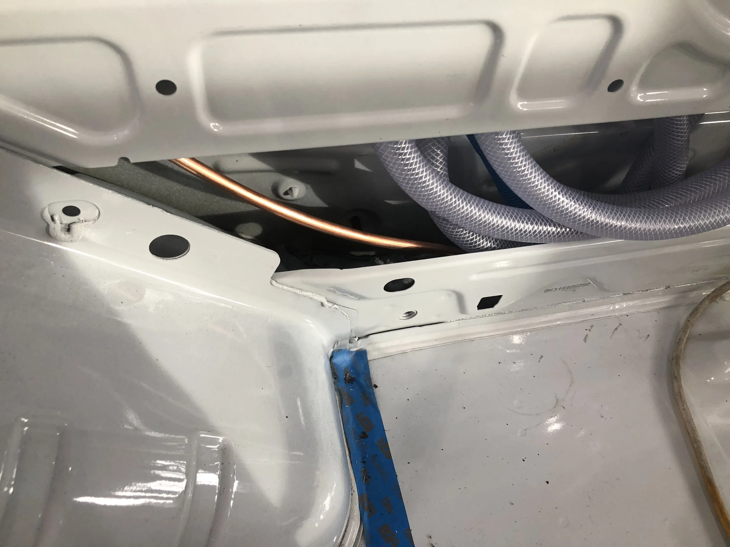
Route the feeder line for the stove along the framing member, crossing over to the outside of the van near the gas tank fill, passing up into the interior wall of the van through the very large 4 x 6 opening in the B pillar
Route the feeder line for the hot water heater directly across the van in front of the rear wheel well, through a hole in the side of the wall, and up into the interior.
Secure all lines with half-inch stainless steel pipe clamps, 1/4” stainless bolts and washers, and 1/4” plus nuts. I use existing holes in the framing where possible, as well as a few 8 mm threaded holes.
Purge the tank at the local propane distributor.
Test for leaks by opening the solenoid, then closing and monitoring the pressure gauge.
I have heat shielding on the propane line where it passes over the exhaust system, but I'm still assessing the need for shielding on the tank itself. I ran the van hot for an hour and couldn't get the surface of the tank to go over ambient temperature, but I will retest in the summer and either add some heat shielding to the tank or extend the exhaust system heatshield.