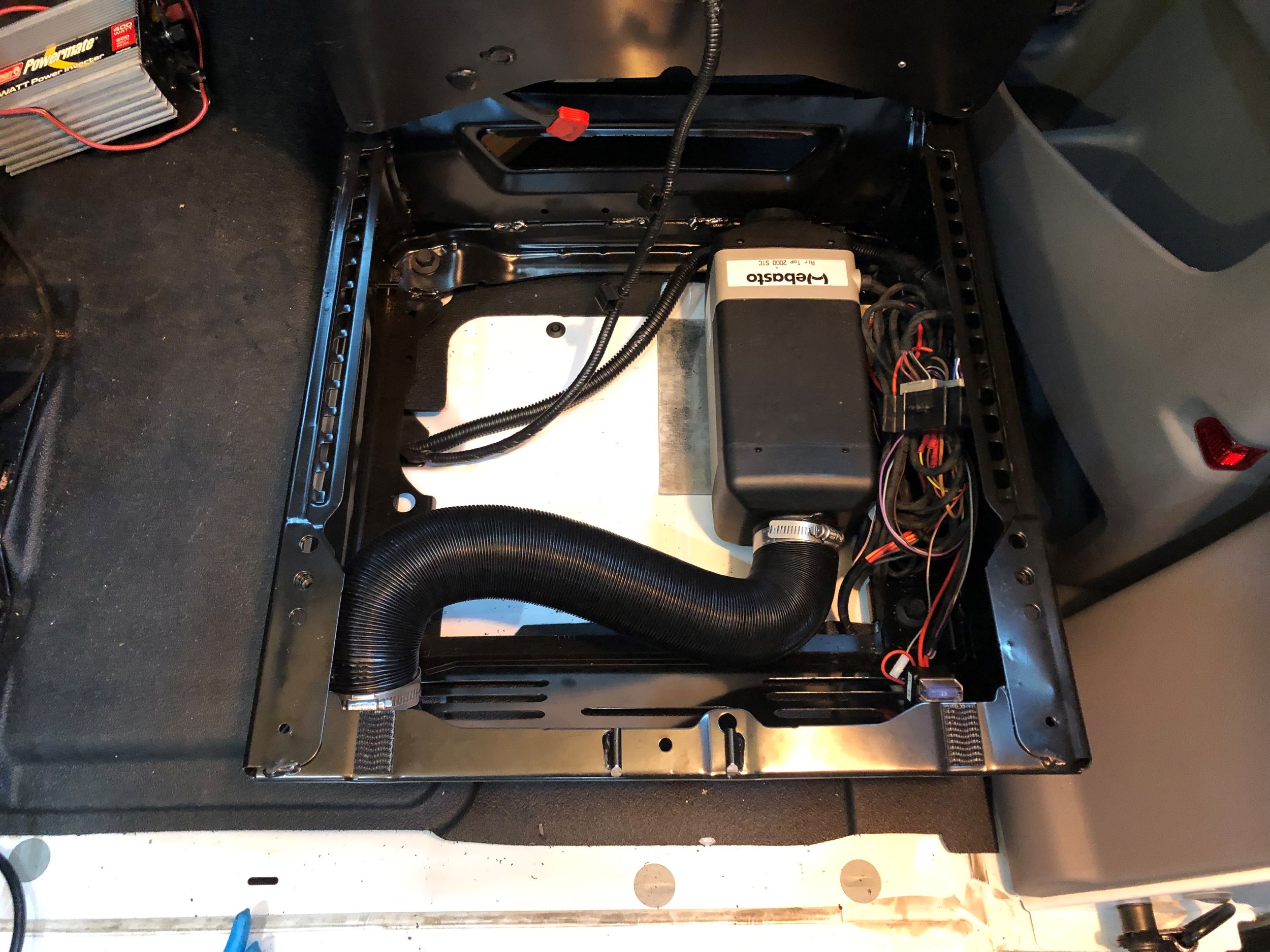
I installed the Webasto Air Top 2000 STC Gasoline heater under the passenger seat.
Materials
Webasto Gasoline heater kit. I purchased mine from a UK company – Heatso. https://www.heatso.com/webasto-air-top-2000-stc-gasoline-petrol-12v-heater-kit/. The kit contains most of the parts necessary for installation with a few exceptions noted below. I also requested the Webasto heater seven day timer, exhaust muffler and flat mounting plate options as part of my purchase.
Improved airflow director. My kit came with a straight director, which isn’t great for a seat base that’s mounted at a 45° angle. I am replacing with this 45 degree grill: http://www.suremarineservice.com/Heat/Grilles/1320204A.html
5/16 to ¼ fuel line reducer connector. The Ford auxiliary fuel port is 5/16 ID. The Webasto uses a 4.5 mm ID fuel line. Gasoline can form vapor bubbles which can impede the flow of fuel, so using this reducer removes a spot where bubbles may form and stick. https://www.amazon.com/gp/product/B076QJ1S66/ref=oh_aui_detailpage_o01_s00?ie=UTF8&psc=1
Ford auxiliary fuel connector – part number CK4Z-9B210-A. https://www.tascaparts.com/oem-parts/ford-kit-ck4z9b210a
2 feet of 5/16 ID fuel line to connect the gas tank to the reducer connector. https://www.amazon.com/Fuel-Inside-Diameter-Length-SAE30R6/dp/B06VVVXFSC/ref=sr_1_5?ie=UTF8&qid=1544725969&sr=8-5&keywords=5%2F16+fuel+line
10 feet ¼” split loom polyethylene to protect the fuel pump power supply
10 feet 3/8” ID fuel line to protect the Webasto fuel line
Stainless cable clamps and zip ties to secure the fuel line and power cable
¾” x 3’ heatshield sleeving to protect the fuel line and power cable where it passes over the exhaust system. https://www.amazon.com/010419-Aluminized-Sleeving-Heat-Sheath/dp/B000E267M4/
Stainless cable clamps, Plusnuts and ¼ stainless bolts and washers to secure the fuel line and power cable
3 1” stainless steel hose clamps for the exhaust muffler and intake silencer. http://www.suremarineservice.com/Heat/Propane-Heater-Install-Parts/1320220A.html. I bought some from Amazon, but they stripped out clamping around the steel exhaust tubing, so I sprung for the $10 Webasto version.
2 2.5” stainless hose clamps for the interior ductwork
2 ½” stainless hose clamps for the 5/16 ID fuel line
Tube of silicone for sealing the mounting plate to the van floor
Primer and paint – I used a can of combined from Rustoleum.
Tools
Drill with drill bits, 2 3/8 inch hole saw, 1” hole saw, and center punch
File or grinding bit to deburr the holes
T40 bit for the seat bolts
Utility knife to cut away the vinyl floor
Wrenches and sockets, particularly ¼ inch drive compact socket handle for bolting in the heater on the underside of the vehicle.
Angle grinder or Dremel with cutoff blade to remove the jack mounting bolt
Car jack with plywood scrap for easily lowering and raising the fuel tank
Process
Remove the passenger seat
Position the seat so that you can reach all four of the bolts holding it down, and loosen the 4 bolts securing it to the seat base. These use a T40 bit.
Unplug the power cable using a 6 mm socket.
Lift the seat up and carry it to the back of the sliding door and set it down. Secure the seatbelt above the sliding door so that you can move in and out of the vehicle without getting strangled. You’ll be jumping in and out a lot.
Prepare the mounting area
Remove the jack and jack mounting plate
Trim off the right hand jack mounting stud using your angle grinder or Dremel
Cut away the vinyl floor. I removed all of the vinyl from underneath the seat, but you really only need to remove the right-hand side where the heater will be placed.
Place the Webasto mounting plate on the floor, sliding the right side of the plate underneath the remaining vinyl
Critical step: you will need to center the mounting plate left/right so that the four Webasto mounting bolts are accessible from underneath the vehicle. You can barely see the spot welds on a seam on the left side of the area from both the underside of the vehicle and within the seat, so that is a partial guide. You also need to center the mounting plate so that the vent port allows sufficient room to secure the vent hose. The intake port will have no hose on it. Once you think you have a good location, drill a pilot hole through the middle of the exhaust port opening in the mounting plate and verify placement under the vehicle. Note that when you are putting the mounting plate down, you will be caulking it to prevent exhaust gases from escaping into the interior from between the mounting plate and the floor of the van. So ideally there is a continuous flat area in some fashion around the seven holes you will be drilling.
Using a marker, mark the drill locations for the four mounting bolts, the fuel line hole, and the intake and exhaust ports.
Remove the mounting plate and drill the holes. Center punch the middle of each hole for accurate drill placement.
Test fit the mounting plate, deburr the holes
Prime and paint the area. I just put some tape over the holes, and sprayed the underside of the vehicle in the area I drilled. Messy but quick.
Once the paint dries, run a contiguous bead of silicone in a circle around the holes, and place the mounting plate in its final location
Attach the fuel pump
Attach 2 feet of 5/16” fuel line to the auxiliary fuel port you ordered from Ford – then put a hose clamp on the fitting. I forgot this step and had to drop the darn tank again.
The fuel tank should be nearly empty to make it easy to handle, 1/8 tank is probably okay, with a total fuel tank and fuel weight of about 45 pounds.
Place a jack or blocks under the fuel tank to support it as you lower it down. I raised the jack to support the tank, and then undid all of the mounting bolts. There are three bolts on each side, with the left side using the longer bolts.
I lowered the tank down about 10 inches, with most of that drop occurring toward the rear where the auxiliary fuel port is located, and the front remaining up high.
Remove the existing auxiliary fuel port plug at the top of the tank, which is blue and yellow, by sliding the yellow clip back, and then pinching the blue parts together and lifting up.
Insert the Ford auxiliary fuel port. You should hear a click. Slide the yellow locking tab forward. Give it a tug to make sure it’s secure.
Determine the final location of your fuel pump. The underside of my frame was already occupied by a propane line and alternator charging cable, so I had to attach my fuel pump to the side of the frame. The fuel pump ideally is mounted level, but should be no more than 45° off level. Leave space on either side of the pump for line routing. On the intake side you will have a short stretch of the Webasto supplied fuel line, the stainless reducer, and then the 5/16 fuel line from the tank.
Drill a hole if necessary for your mounting location. If you do need to drill into the side of the frame as I did, be warned that it appears to be hardened steel and took me about 15 minutes of solid drilling and grunting.
Attach the fuel pump
Attach and clamp the short segment of Webasto fuel line to the intake side, then insert the 5/16 to ¼ reducer and clamp, and then attach the 5/16 fuel line and clamp. The Webasto instructions state that any fittings should minimize bubble possibility by jamming the barbed fittings together inside of the rubber hose. So I trimmed the hoses where necessary to achieve this.
Lift the tank back up and reattach to vehicle. I did not bother to track down the torque specifications for these bolts, just cranked them down as tight as I could with a half-inch bar.
Run the fuel line and wiring
Briefly, I ran the fuel line and wiring from the Webasto unit over the top of the exhaust system and then along the frame on the left side.
Wrap the fuel pump wiring harness in ¼” split loom
Feed the Webasto fuel line through the 3/8 fuel line
Take both the fuel line and wiring harness and attach to the fuel pump
Feed and attach the lines as you go. I try to keep future maintenance in mind so that dealers and others who work on my vehicle don’t need to remove any work I do. In this case that meant running the fuel lines above any Ford OEM brake lines and wiring harnesses. I already had other lines in place, so I zip tied these lines to my existing attachment points.
When I got to the area the exhaust system, I slid on the 3 feet of heatshield, and fed it over the top of the exhaust system. The left-hand side of the run is well supported by the emergency brake bracket. But I needed to install a pipe clamp through the floor the vehicle to hold the right hand side of the lines off of the exhaust system
Make sure to extend the heatshield to the Webasto unit. The Webasto exhaust line gets quite hot and you’ll be glad of the extra protection since the space is so tight up there.
Test the fuel pump by sending about 150 12V pulses through the line. Each time you make the connection the pump solenoid will click. Eventually the fuel will make its way to the end of the line. You might need more than 1/8 of a tank for this to work though. By testing now, you both verify there are no kinks in your installation, and when you test fire the main unit you won’t have to deal with fault codes while it pumps the fuel.
Don’t attach the fuel line and electrical at this point. The exhaust and intake lines are probably easier to install without these in the way.
Mount the heater and attach lines
Place the heater on top of the mount with the rubber gasket in place
On the underside of the vehicle, bolt the heater in. I was able to use ¼ inch drive socket for this. Don’t be too vigorous with your bolting, since the floor has ridges in it, you could deform the mounting plate or even break the heater casting.
Remove the fuel power cable which is stuffed up inside of the intake port, and push it into its slot.
Trim the intake hose to the necessary length. To protect my intake from splashing and high water from fording rivers, I am using the supplied intake silencer and a very short length of hose.
Attach the intake hose to the Webasto unit with the supplied clamp, attach the intake silencer to the hose with your own clamp, and then zip tie the intake silencer to the frame
Attach the exhaust hose to the Webasto unit with the supplied clamp
Attach the exhaust muffler to the frame. The exhaust muffler must be mounted level. I drilled a hole at the base of the B pillar and made a small aluminum bracket to mount it.
Trim the exhaust hose and fit to the exhaust muffler. I recommend making the hose a bit long to provide pushing tension, as my clamps don’t seem to compress this material well.
Trim the remainder of the exhaust hose to the desired length and attach to the other side of the muffler. Webasto states that there should be no low spots in the run where condensation could build up. And the end of the exhaust hose must point directly downward. I attached mine to the side of my factory step with a number 10 stainless bolt and cable clamp.
Attach the fuel line and wiring.
Drill a 2 3/8” hole in the seat base at the desired vent location.
Install the grill
Trim the vent hose to fit in attach using your own hose clamps.
Route the electrical wiring
I chose to install my Multi-control unit on the forward face of the overhead cabinet by the sliding door. I didn’t want the green glow of the panel to be visible while sleeping, and I also wanted the temperature sensor to be closer to the sleeping area.
You can either cut the end off of the Webasto wiring harness and reattach later, or run your own wires. I chose to run my own wires so that if I damaged them or the Webasto length was insufficient I wouldn’t have to do over. I ran a total of five wires – 2 14awg power lines and 3 18awg control lines for the multi-control. I wrapped the wires in electrical tape because I wasn’t sure the split loom would fit down the B pillar, but in hindsight I should’ve tried that first as I’m not happy with the abrasion resistance of the electrical tape.
Remove the middle and bottom sections of trim from the passenger side B pillar. Gentle prying with a trim removal tool worked for me although I broke one clip. The middle panel is removed first, and then the bottom panel.
Insert a fish tape into the space above the sliding door. With enough cursing and patience, you can fish the tape down into the B pillar where it will become visible around the seatbelt retraction area. I had some help because I cut a hole in the B pillar to mount a light switch so I could see the tape through the hole. There are multiple layers of metal to pass through, so you have to pick the right passage that connects directly to the B pillar.
Pull the wires up into the area above the sliding door, and then run your fish tape again from your final location to this spot to complete the pull.
Lift the vinyl floor between the seat and the B pillar and feed the wires underneath the vinyl.
Reattach the Multi-control plug to your 3 wires, and plug in the multi control.
Provide ground power to your 2 power leads
Power up and test the unit
Secure the Webasto supplied fuse block to the side of the seat base where it’s accessible with the seatin place. I used VBO tape.
Hook up the red lead to positive, and the Brown lead to negative.
Plug in your control unit and turn the unit on.
The multi-control needs a bit of setup - date/time, selection of your Webasto model.
Since I had already primed the fuel line, mine fired off immediately. I could hear the fuel pump ticking, the fan started spinning up, and after about a minute warm air started to flow.
I let it run for a couple of hours, and checked underneath the vehicle for any temperature problems. I realized how hot the exhaust got and did what I could to move the fuel line away from the exhaust hose.